
Your first robot: The driver [4/5]
by Kyle Fazzari on 9 March 2018
Please note that this blog post has out technical information that may no longer be correct. For latest updated documentation about robotics in Canonical please visit https://ubuntu.com/robotics/docs.
This is the fourth blog post in this series about creating your first robot with ROS and Ubuntu Core. In the previous post we worked on getting data out of the wireless controller and into ROS in a format meant for controlling differential drive robots like ours: the Twist message. Today we’re going to create a ROS node that takes that Twist message and turns it into the appropriate wheel speeds to drive our robot.
Remember that this is also a video series, feel free to watch the video version of this post:
Alright, let’s get to it. There are a number of ways we could tackle this problem. If we were working on making our robot autonomous, we might use ros_control. However, it would add several more parts to this series, and we just don’t have the sensors available to make it worthwhile. Let me explain.
Open-loop versus closed-loop
Controlling a robot is always a loop of tasks done over and over again. For example, once we’re done with this blog post, our loop will look something like this:
- Read data from controller
- Turn controller data into velocity data
- Turn velocity data into wheel speeds
- Turn wheel speeds into duty cycles
- Change the wheel duty cycle
- Return to step 1
There are two types of control loops: open or closed. The difference is that a closed loop has feedback in it. As a simple example, let’s say you wanted to make some hot cocoa (it’s that time of year!) in the microwave. If you have a microwave like mine, you put the cocoa in, set the timer for a few minutes and come back when it’s done. The control loop of that microwave looks something like this:
- Set power level to 10
- Is time up yet? If not, return to step 1
There’s no feedback mechanism here: this is an example of open-loop control. The microwave is heating the cocoa only for a set amount of time, and that’s all it cares about. In fact, I often find it not hot enough and end up putting it back in.
However, maybe you have a fancy microwave. Maybe it includes a thermal sensor of some kind, perhaps a probe that you insert into the cocoa when you put it inside the microwave (gross). Now the microwave can determine the temperature of the cocoa, which means you no longer have to set a timer, you just need to tell the microwave how hot you like your cocoa. Insert your desired temperature, and now the microwave’s control loop might look something like this:
- Set power level to 10
- How hot is the cocoa? Has it yet reached the desired temperature? If not, return to step 1
That thermal sensor gives the microwave some data for feedback in its loop, which means this is closed-loop control. This is probably the simplest one you can imagine, but there’s an entire field dedicated to closed-loop control, called control theory.
On our robot, we have no sensors that reasonably give us a way to determine a change in position. For example, if we had sensors on the wheels that told us how quickly they were spinning, we could use our knowledge of the wheel size to estimate how fast we’re going (this is called odometry). Since we have no such data, we have nothing to feed back: we’re limited to open-loop control right now.
That’s why using ros_control isn’t worth the effort: we don’t have the data necessary to close the loop, so we might as well just write our own super-simple open-loop controller instead. So let’s get on with it, shall we?
Prerequisites
There’s really only one new prerequisite here: a little more Python knowledge. We’ve kept it as simple as we could until now, but it’s time for our code to grow up a little. You’re already familiar with functions after following the worksheets. Today we’re going to use classes. Read this tutorial on classes, if needed.
Step 1: Calculate wheel speeds from Twist
Thanks to part 3, we have the controller generating Twist messages, which represent the desired linear and angular velocity of the robot (“go this fast forward/backward”, “turn this fast left/right”). At the end of the day, the only way the robot moves at all is by changing wheel direction and speed. We need to develop a way to convert the commanded velocities into wheel speeds that actually accomplish what was commanded. To do that, we need just a smidge of math.
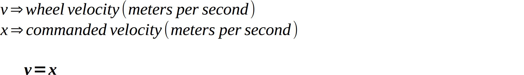
Let’s talk about the linear velocity first, since it’s pretty simple. If we command the robot to move forward at 1 meter per second (m/s), in what direction (forward or backward) and at what speed (in m/s) does each wheel need to move? The answer should be intuitive: both wheels need to spin forward at 1m/s. So the formula for the linear velocity part of the wheel velocity is simply:
Angular velocity is a little more tricky.
If we command the robot to turn left at 90 degrees per second, in what direction (forward or backward) would each wheel need to turn? The answer is fairly intuitive, but it depends on how we want to make our robot turn. There are two options: single-wheel turning and double-wheel turning.
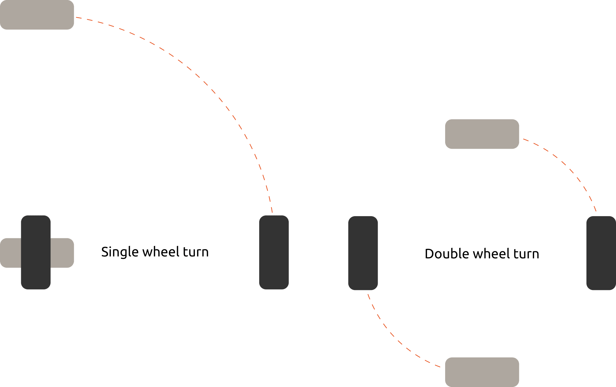
As you can see in the picture, above, single-wheel turning involves leaving one wheel stationary, and turning the other. Double-wheel turning involves rotating both wheels in opposite directions, thus sharing the work of the turn. If we elected to use single-wheel turning, then the answer to the question would be “The left wheel doesn’t turn at all, and the right wheel turns forward.” However, I prefer the double-wheel method, so my answer is “The left wheel turns backward, and the right wheel turns forward.”

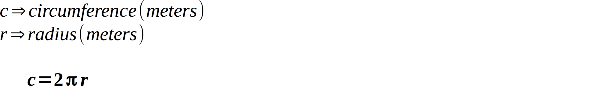
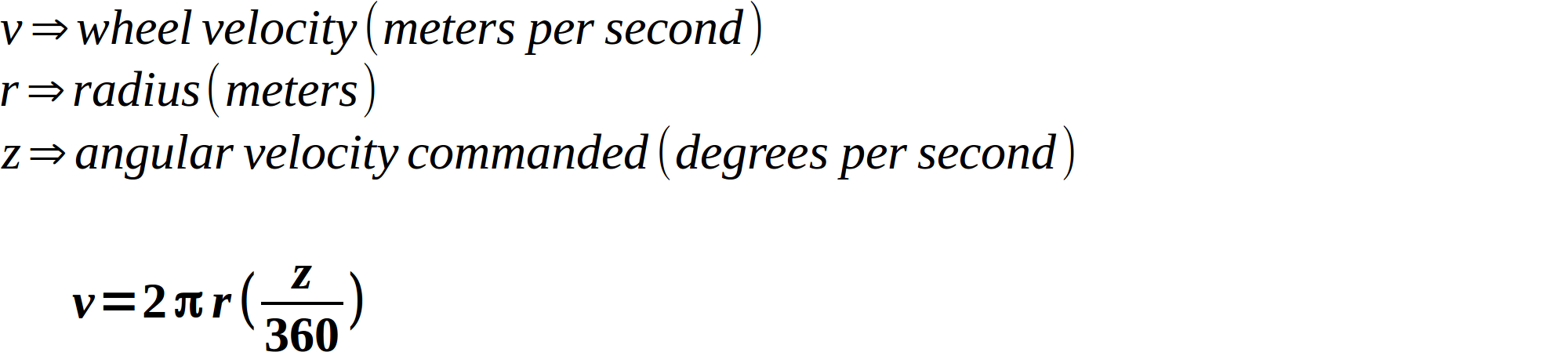
Okay, we have the wheel directions. Now for the speed: if we command the robot to turn left at 90 degrees per second, at what speed (in meters per second) would each wheel need to turn? Note that this turn is a portion of a circle, the outside of which traces the desired path for our wheels. Recall the formula for the circumference of a circle:
How big of a portion of the circle are we wanting to turn? Well, we know that 360 degrees is an entire circle, so we can use a ratio and combine it with the circumference to create our formula for wheel speed (which is really just the formula for the length of an arc):
Alright, there’s only one more unknown in this formula: the radius. What is it? You can see that it’s actually half the distance between the two wheels (called the “track”). So our formula turns into this:
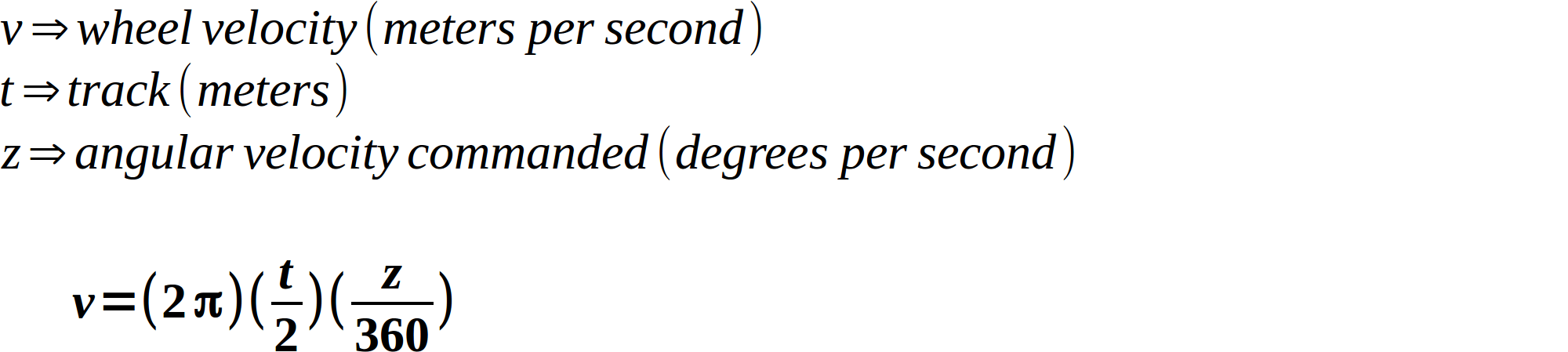
Awesome! Using this, we can now answer the question. I measured my robot’s track to be 0.091 meters. Using that, I calculate that the left wheel should be turning backward at 0.071 m/s, and the right wheel should be turning forward at the same speed.
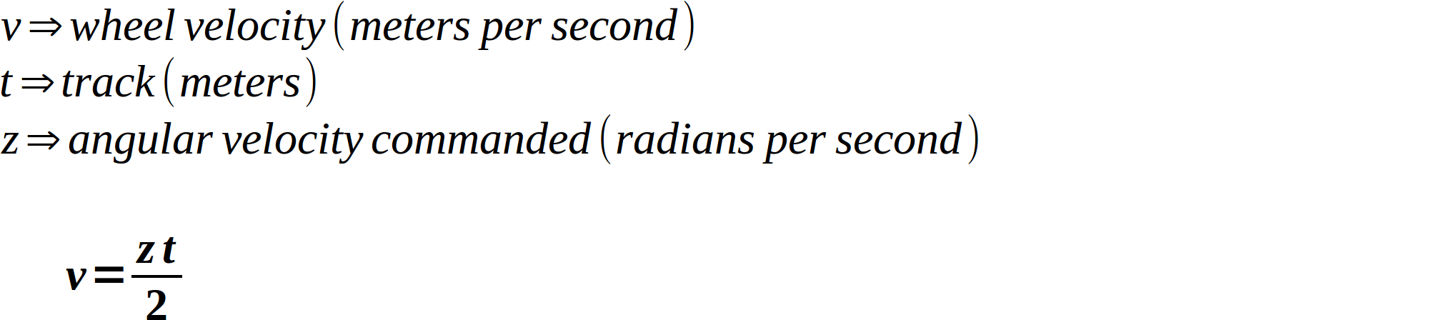
We can actually simplify this formula, because the Twist message specifies angular velocities in radians per second as opposed to degrees. 360 degrees = 2π radians. If we change our ratio to use radians, things start canceling beautifully:
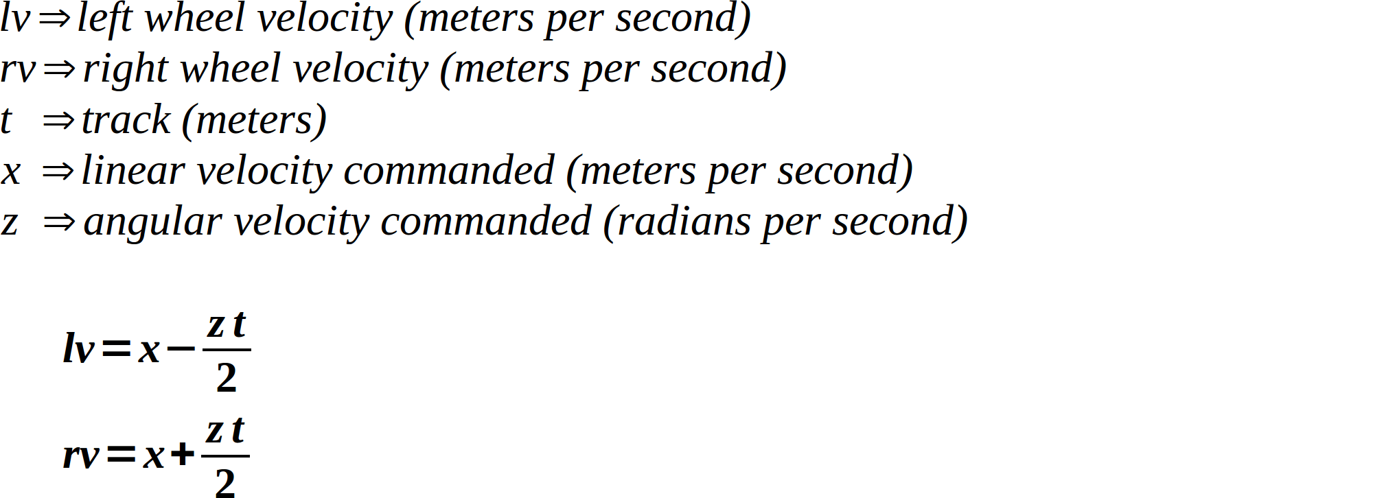
In addition, ROS conventions follow the right-hand rule, which means that a positive angular velocity means a counter-clockwise turn, and a negative angular velocity means a clockwise turn. Let’s decide right now that a positive value means that our wheels turn forward, and a negative value turns them backward. Using these two facts along with our formulas, we can come up with formulas for both wheel speeds:
Step 2: Convert wheel speeds into duty cycles
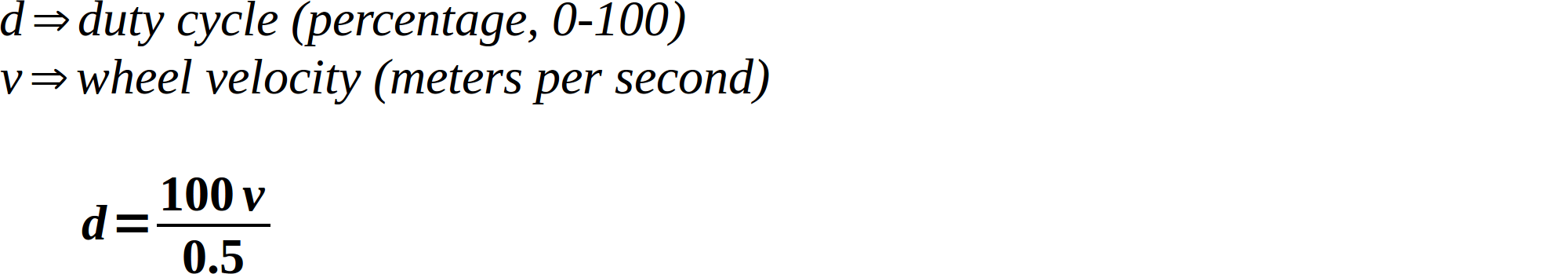
We got most of the math out of the way, but now we have a small issue that requires our attention. Our wheel speeds are in meters per second, but as you learned in CamJam worksheet #7, the way we actually control the motors is by applying a duty cycle between 0 and 100 (stopped and full speed, respectively). How do we get from meters per second to duty cycles? This is where closed-loop control would come in handy: if we had wheel speed sensors, we could compare how fast the robot was going to how fast it should be going, and say “it needs a higher duty cycle” or “it needs a smaller duty cycle”. However, we already discussed that this needs to be an open-loop controller. We need to get our duty cycle by making some assumptions instead of using feedback data. We’ll do this by determining our robot’s maximum possible speed, and obtain the duty cycle by dividing the requested speed by the maximum speed.
How do we determine our robot’s maximum speed? The most accurate way would be to actually measure it. Essentially, measure out a meter, set the vehicle at the beginning, get out your stopwatch, and do a drag race.
Just for simplicity’s sake, though, we can cheat a little. If you noticed from part 3, by default the data from the controller has a maximum value of 0.5. So if we see a 0.5, we know the controller is maxed out. So if we just assume that our robot’s maximum speed is 0.5 meters per second, maxing out the controller will also max out our robot’s speed. It’s a little dirty, but it works for our case since we’re only using a controller anyway.
Step 3: Add geometry_msgs as a dependency
We’re about to rewrite the “driver” node we started in part 2 to handle Twist messages instead of String messages. This requires changing the std_msgs dependency of our edukit_bot package to geometry_msgs. Open up the edukit_bot package’s package.xml file and make it look something like this:
<?xml version="1.0"?>
<package>
  <name>edukit_bot</name>
  <version>0.1.0</version>
  <description>The edukit_bot package</description>

  <maintainer email="you@you.com">You</maintainer>

  <license>GPLv3</license>

  <buildtool_depend>catkin</buildtool_depend>
  <build_depend>rospy</build_depend>

  <exec_depend>rospy</exec_depend>
  <exec_depend>geometry_msgs</exec_depend>
  <exec_depend>python-rpi.gpio</exec_depend>
</package>
This is saying “I require catkin and rospy in order to build, and I require rospy, geometry_msgs, and python-rpi.gpio in order to run.”
Step 4: Write the driver
Now that we have the math out of the way, let’s write the ROS driver that utilizes it. In fact, we’ll rewrite the “driver” node in the edukit_bot package that we started in part 2. First, activate that workspace:
$ cd ~/edukit_bot_ws
$ source devel/setup.sh
Now make the ~/edukit_bot_ws/src/edukit_bot/src/driver_node file look like this (note that the entire package created in this part is available for reference):
#!/usr/bin/env python

import rospy
from geometry_msgs.msg import Twist

import RPi.GPIO as GPIO


# Set the GPIO modes
GPIO.setmode(GPIO.BCM)
GPIO.setwarnings(False)

_FREQUENCY = 20


def _clip(value, minimum, maximum):
    """Ensure value is between minimum and maximum."""

    if value < minimum:
        return minimum
    elif value > maximum:
        return maximum
    return value

class Motor:
    def __init__(self, forward_pin, backward_pin):
        self._forward_pin = forward_pin
        self._backward_pin = backward_pin

        GPIO.setup(forward_pin, GPIO.OUT)
        GPIO.setup(backward_pin, GPIO.OUT)

        self._forward_pwm = GPIO.PWM(forward_pin, _FREQUENCY)
        self._backward_pwm = GPIO.PWM(backward_pin, _FREQUENCY)

    def move(self, speed_percent):
        speed = _clip(abs(speed_percent), 0, 100)

        # Positive speeds move wheels forward, negative speeds
        # move wheels backward
        if speed_percent < 0:
            self._backward_pwm.start(speed)
            self._forward_pwm.start(0)
        else:
            self._forward_pwm.start(speed)
            self._backward_pwm.start(0)

class Driver:
    def __init__(self):
        rospy.init_node('driver')

        self._last_received = rospy.get_time()
        self._timeout = rospy.get_param('~timeout', 2)
        self._rate = rospy.get_param('~rate', 10)
        self._max_speed = rospy.get_param('~max_speed', 0.5)
        self._wheel_base = rospy.get_param('~wheel_base', 0.091)

        # Assign pins to motors. These may be distributed
        # differently depending on how you've built your robot
        self._left_motor = Motor(10, 9)
        self._right_motor = Motor(8, 7)
        self._left_speed_percent = 0
        self._right_speed_percent = 0

        # Setup subscriber for velocity twist message
        rospy.Subscriber(
            'cmd_vel', Twist, self.velocity_received_callback)

    def velocity_received_callback(self, message):
        """Handle new velocity command message."""

        self._last_received = rospy.get_time()

        # Extract linear and angular velocities from the message
        linear = message.linear.x
        angular = message.angular.z

        # Calculate wheel speeds in m/s
        left_speed = linear - angular*self._wheel_base/2
        right_speed = linear + angular*self._wheel_base/2

        # Ideally we'd now use the desired wheel speeds along
        # with data from wheel speed sensors to come up with the
        # power we need to apply to the wheels, but we don't have
        # wheel speed sensors. Instead, we'll simply convert m/s
        # into percent of maximum wheel speed, which gives us a
        # duty cycle that we can apply to each motor.
        self._left_speed_percent = (100 * left_speed/self._max_speed)
        self._right_speed_percent = (100 * right_speed/self._max_speed)

    def run(self):
        """The control loop of the driver."""

        rate = rospy.Rate(self._rate)

        while not rospy.is_shutdown():
            # If we haven't received new commands for a while, we
            # may have lost contact with the commander-- stop
            # moving
            delay = rospy.get_time() - self._last_received
            if delay < self._timeout:
                self._left_motor.move(self._left_speed_percent)
                self._right_motor.move(self._right_speed_percent)
            else:
                self._left_motor.move(0)
                self._right_motor.move(0)

            rate.sleep()

    def main():
        driver = Driver()

        # Run driver. This will block
        driver.run()

if __name__ == '__main__':
    main()
Okay, that probably looks pretty new. Why don’t we break it down piece by piece.
#!/usr/bin/env python

import rospy
from geometry_msgs.msg import Twist

import RPi.GPIO as GPIO


# Set the GPIO modes
GPIO.setmode(GPIO.BCM)
GPIO.setwarnings(False)

_FREQUENCY = 20
This is more or less straight out of part 2, although we’re importing the Twist message now instead of String. We’re also saving the frequency into a more conventionally-named variable, _FREQUENCY (the underscore indicates that it’s for internal use only, all-caps indicates that it’s a constant).
def _clip(value, minimum, maximum):
    """Ensure value is between minimum and maximum."""

    if value < minimum:
        return minimum
    elif value > maximum:
        return maximum
    return value
The _clip function is pretty simple: it makes sure a given value is between the given minimum and maximum. We’ll use it later to make sure we don’t try to make the motors move with a duty cycle less than 0 or greater than 100.
class Motor:
Here we’re creating a new class to represent a motor that we can move.
    def __init__(self, forward_pin, backward_pin):
        self._forward_pin = forward_pin
        self._backward_pin = backward_pin

        GPIO.setup(forward_pin, GPIO.OUT)
        GPIO.setup(backward_pin, GPIO.OUT)

        self._forward_pwm = GPIO.PWM(forward_pin, _FREQUENCY)
        self._backward_pwm = GPIO.PWM(backward_pin, _FREQUENCY)
This is the initializer for the Motor class. It’s called automatically whenever a new instance is created. It accepts two parameters, one for each pin involved in moving the motor (one forward, one backward). It then sets the pins up as outputs, and saves off the PWMs for use in the move() function:
    def move(self, speed_percent):
        speed = _clip(abs(speed_percent), 0, 100)

        # Positive speeds move wheels forward, negative speeds
        # move wheels backward
        if speed_percent < 0:
            self._backward_pwm.start(speed)
            self._forward_pwm.start(0)
        else:
            self._forward_pwm.start(speed)
            self._backward_pwm.start(0)
This is the main worker function of the Motor class: it’s how the motor moves. It accepts a positive or negative percent (between 0-100), where a positive value moves forward, and a negative value moves backward. Here’s where we utilize the _clip() function we discussed above to ensure the percentage requested does not fall outside the valid range of 0-100, which turns it into a valid duty cycle.
class Driver:
Here’s one more class, representing the ROS driver itself.
    def __init__(self):
        rospy.init_node('driver')

        self._last_received = rospy.get_time()
        self._timeout = rospy.get_param('~timeout', 2)
        self._rate = rospy.get_param('~rate', 10)
        self._max_speed = rospy.get_param('~max_speed', 0.5)
        self._wheel_base = rospy.get_param('~wheel_base', 0.091)

        # Assign pins to motors. These may be distributed
        # differently depending on how you've built your robot
        self._left_motor = Motor(10, 9)
        self._right_motor = Motor(8, 7)
        self._left_speed_percent = 0
        self._right_speed_percent = 0

        # Setup subscriber for velocity twist message
        rospy.Subscriber(
            'cmd_vel', Twist, self.velocity_received_callback)
Here’s the initializer for the Driver class, called automatically when a new instance is created. It doesn’t accept any parameters, since it supports changing its behavior by way of parameters from the ROS Parameter Server (which you learned a bit about in ROS tutorial number 7). We start out by initializing the ROS node, which begins communication with the ROS master. We then record the current time (which we’ll use later) and retrieve the values for all the parameters we support. After that, we create two instances of the Motor class defined above to represent the left and right motors, and initialize our speeds to zero.
A quick aside: these pins correspond to which motor is motor A, which is motor B, and the polarity that we used to hook them up. If you happened to connect yours differently than I connected mine (which is perfectly fine), you may need to switch these pins around a little or your robot will move hilariously badly.
Finally, we subscribe to our Twist topic, which is called cmd_vel (following convention, it means “commanded velocity”), and request that the velocity_received_callback() function is called whenever a new command is received.
    def velocity_received_callback(self, message):
        """Handle new velocity command message."""

        self._last_received = rospy.get_time()

        # Extract linear and angular velocities from the message
        linear = message.linear.x
        angular = message.angular.z

        # Calculate wheel speeds in m/s
        left_speed = linear - angular*self._wheel_base/2
        right_speed = linear + angular*self._wheel_base/2

        # Ideally we'd now use the desired wheel speeds along
        # with data from wheel speed sensors to come up with the
        # power we need to apply to the wheels, but we don't have
        # wheel speed sensors. Instead, we'll simply convert m/s
        # into percent of maximum wheel speed, which gives us a
        # duty cycle that we can apply to each motor.
        self._left_speed_percent = (100 * left_speed/self._max_speed)
        self._right_speed_percent = (100 * right_speed/self._max_speed)
This is the velocity_received_callback() function, part of the Driver class. Thanks to our subscription in __init__(), this function is called whenever a new command message comes in. Here’s where the math we did in steps 1 and 2 come into play. First of all, we record the time we received the message (which we’ll discuss in a moment). Then we extract the linear and angular velocity components out of the message. Using this information, we use the wheel speed formula we derived in step 1 to calculate the left and right wheel speeds (in meters per second). Then we use the duty cycle formula derived in step 2 to turn those wheel speeds into left and right percentages. Since these values can be negative, they represent both the desired duty cycle as well as wheel direction.
Note that this function doesn’t actually change the wheel speeds at all, it just calculates what they should be. Why? We’ll discuss that in a moment.
    def run(self):
        """The control loop of the driver."""

        rate = rospy.Rate(self._rate)

        while not rospy.is_shutdown():
            # If we haven't received new commands for a while, we
            # may have lost contact with the commander-- stop
            # moving
            delay = rospy.get_time() - self._last_received
            if delay < self._timeout:
                self._left_motor.move(self._left_speed_percent)
                self._right_motor.move(self._right_speed_percent)
            else:
                self._left_motor.move(0)
                self._right_motor.move(0)

            rate.sleep()
This is the control loop of our Driver class. It’s where we actually apply the newly-calculated wheel speeds, in a loop that runs at a specific rate (10 Hz by default). What if we don’t receive a new commanded velocity by the time we loop again? We just use the previously-commanded one. That seems a little odd– why do we have a loop at all if we only ever use the commanded velocity?
Let’s say we pulled this logic out of the loop and put it in the message handler (the velocity_received_callback() function) instead. What happens if we received a few commanded velocities, but then the network went down, or we otherwise lost communication with the controller? The robot would just continue moving at the previously-commanded velocities, and you would have to go chase it down. I’ve had that happen on a robot that weighed several hundred pounds– it went out of range of the control unit and just kept on trucking. Boy did I learn my lesson.
By putting this logic in a loop, and recording when commanded messages come in, we can implement a timeout to make sure our robot never runs away from us if issues occur. You can see this in the loop: we calculate how long it’s been since we last received a commanded velocity. If it’s less than the timeout (2 seconds by default) the calculated wheel speeds are used. If it’s greater than the timeout (i.e. we haven’t received a message for a while), then we halt the robot.
def main():
    driver = Driver()

    # Run driver. This will block
    driver.run()
This is the main part of the program, where we simply create a new instance of the Driver class and start its control loop.
if __name__ == '__main__':
    main()
This is the entry point of this whole node– we simply run the main() function.
Alright, we’re done with this node. Let’s build it before moving on:
$ cd ~/edukit_bot_ws
$ catkin_make
Step 5: Test the driver node
As in part 2, we need to make sure we have permission to access GPIO as a user (remember this resets upon reboot):
$ sudo chmod a+rw /dev/gpiomem
We’re also going to use what we learned in part 3 to get the controller giving us Twist messages. Open up four terminals running the classic shell. In the first one, run roscore:
$ roscore
In the second, run the joy node:
$ rosrun joy joy_node
[ INFO] [1515003691.568172834]: Opened joystick: /dev/input/js0. deadzone_: 0.050000.
In the third, run the teleop node:
$ rosrun teleop_twist_joy teleop_node
[ INFO] [1515003734.469189240]: Teleop enable button 0.
[ INFO] [1515003734.469664500]: Linear axis x on 1 at scale 0.500000.
[ INFO] [1515003734.469924707]: Angular axis yaw on 0 at scale 0.500000.
And finally, in the fourth terminal activate our workspace and run our new driver node:
$ cd ~/edukit_bot_ws
$ source devel/setup.sh
$ rosrun edukit_bot driver_node
Now turn on your controller and start moving your robot around! Oh wait, you tried to turn and nothing happened? Right, let me explain.
Remember in step 2 how we used the fact that the twist messages we were getting with the controller maxed out at 0.5? That works great for linear velocities, but the controller also maxes out at 0.5 radians per second for its angular velocity, which is so slow that the motors can’t actually pull it off (they just give off a quiet buzzing sound instead, as if they want you to know that they’re doing their best).
The solution is to request the teleop node to scale those values to more reasonable turning speeds. Go to the terminal where you ran the teleop node, ctrl+c it, and re-run it with an angular scaling factor. You can experiment with this to see how responsive/twitchy you like your robot, but I settled on a value of 4 (larger values will make it more sensitive):
$ rosrun teleop_twist_joy teleop_node _scale_angular:=4
[ INFO] [1515005430.818803229]: Teleop enable button 0.
[ INFO] [1515005430.819282707]: Linear axis x on 1 at scale 0.500000.
[ INFO] [1515005430.819531978]: Angular axis yaw on 0 at scale 4.000000.
NOW you should be able to successfully drive it around.
In the next (and final) post in this series, we’ll talk about how launch files save us from having to open a billion terminals just to run a few ROS nodes, and turn our ROS package into a snap that starts on boot and is easily installed by your friends!
This article originally appeared on Kyle Fazzari’s blog.